Determining Number & Location of Hose Connections | NFPA 14
Determining Number & Location of Hose Connections According to NFPA 14

Determining Number & Location of Hose Connections according to NFPA 14
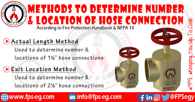
Codes and standards employ two approaches to determining hose connection locations (The Actual Length Method & The Exit Location Method).
The Actual Length Method:
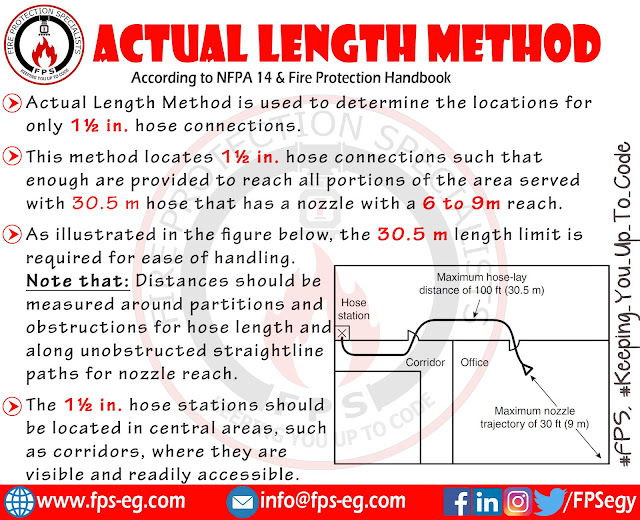
Actual Length Method is used only for determining number and locations of 1½ in. hose connections.
This method locates 1½ in. hose connections such that enough are provided to reach all portions of the area served with a 30.5 m hose that has a nozzle with a 6- to 9-m reach.
As illustrated in the figure below, the 30.5 m length limit is required for ease of handling. Noting that: Distances should be measured around partitions and obstructions for hose length and along unobstructed straightline paths for nozzle reach.
The 1½ in. hose stations should be located in central areas, such as corridors, where they are clearly visible and readily accessible.
 |
| Actual Length Method |
Exit location method
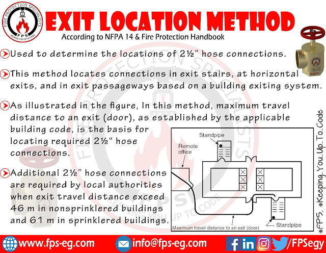
Exit location method is used for 2½ in. hose connections, this method locates connections based on a building’s exiting system.
Using this method, 2½ in. hose connections are located in exit stairs, at horizontal exits, and in exit passageways, as required by the building code, This location allows fire fighters to connect to a system in relative safety and to have a charged hose available before entering a fire area.
As illustrated in the figure below, In the exit location method, maximum travel distance to an exit (door), as established by the applicable building code, is the basis for locating required 2½ in. hose connections.
 |
| Exit Location Method |
NFPA 14 permits additional 2½ in. hose connections to be required by local authorities when exit travel distances exceed 46 m in nonsprinklered buildings and 61 m in sprinklered buildings.
If additional connections outside of exit enclosures are considered necessary, they should be located only in areas protected by fireresistive construction so that fire fighters will have a protected environment in which they can connect hoses.
Locating of hose standpipe outlets at roof
The roof should be treated as an additional floor.
According to NFPA 14, roof outlets can be omitted where the roof pitch is greater than 3 in 12. An additional outlet must be provided at the top of the standpipe for testing purposes. This outlet will permit flowing 500 gpm.
Positioning of Hose Connections at Landings.
NFPA 14 permits to place connections at intermediate floor landings.
This placement allows hoses to be connected somewhat below the fire floor while minimizing the additional hose length required to do so.
It also avoids congestion problems associated with having hose connections located adjacent to exit doors and areas of wheelchair refuge within stairwells. Locating hose connections in this manner also prevents kinking hose, as it bends around doorways.
Installation height of hose connections & hose stations
Installation height of hose connections and hose stations shall be as per the following figure:
 |
| Installation height of hose connections & hose stations |
References of the article:
NFPA 14 - 2019 edition (Standard For The Installation of standpipe and Hose Systems)
Fire Protection Handbook, 20th Edition
Read Also:
Class II Standpipe System according to NFPA 14
Where Standpipe System is Required?
Fire Department Connection For Standpipe System
Floor Control Valve Assembly According to NFPA 13
Sectional Drain & Floor Cotrol Valve Assembly Drain


004861F0C1
ReplyDeletekiralık hacker
hacker arıyorum
kiralık hacker
hacker arıyorum
belek